Day 23
Dimensioning
Dimensions you included on the drawing affect how your design is manufactured.
A drawing released for production must show the object in its completed state and contain all necessary information for specifying the final part. The information communicated through the technical drawing must provide functional annotations that can be read by the manufacturer without any misinterpretation, ensuring the part is produced as you intended.
Keep in mind:
- The finished object.
- The function of the part in the total assembly.
- How you will inspect the final part to determine its acceptability.
- Production processes.
When a finished object is measured, it will always vary slightly from the exact dimensions specified (see section on tolerances below for more information).
- Dimensions are placed in the views and sections where the detail is clearly described by visible lines.
- The function of the object is secured by directional dimensioning, and can be measured when inspected.
- Dimensions are not to be repeated, and information of a dimension shall not be given in two different ways.
Tolerance is the total amount that the feature on the actual part is allowed to vary from what is specified by the drawing.
Ref. Technical Drawing with engineering Graphics, 2016 p. 505.
Such information dimensions shall be enclosed in a parenthesis. |
|
|
Dimensioning Symbols
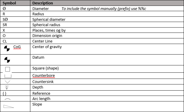
Symbols are used together with dimensions to replace traditional terms and abbreviations.
An overview of the most used symbols can be seen in the image below.
 |
Holes
Dimensioning of holes can be clearly communicated by use standard symbols.
|
 |
Threads
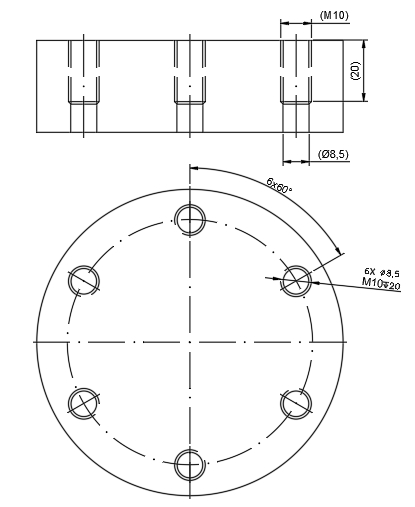
When producing an inner thread, as displayed below, one first has to drill a hole in the material. After one has drilled the hole with the correct diameter drill bit, one can then tap it to create threads in it. The size of the drill bit used to create the initial hole is defined through standards. It is therefore not required to include information regarding the diameter of the drill bit used for drilling the hole prior to tapping it, as the standards defining it are available to the workshop. One also has to bear in mind that a thread will never be fully threaded as long as it has a defined depth. Due to the tapping process the last bit of the hole will not be threaded. The most cost efficient way display a thread is therefore by dimensioning the required depth of the thread, leaving the workshop to decide the depth of the initial hole. The image below displays a part where the initial hole prior to tapping goes through the whole length of the material. The threading on the other hand is only has a depth of 20mm. Because of this the diameter of the drilling hole is displayed (8,5mm).
|
 |
Threads are normally standardized to suit different area of applications.
- Maskintegning includes technical tables for Metric ISO threads, Unified threads (inches) in addition to standard holes for bolted connections.
- For more information regarding fasting materials can you also look at the Tingstad catalog,
Technical Information. Tingstad AS is a widely-used supplier of fastening materials.
More information regarding drawing and dimensioning of threads are described in Maskintegning, Section 25.4 Tegning av gjengede deler and 25.5 Målsetting av gjenger.
Datum Point - Datum Surface
|
Datum Surface symbols are capital letters (A, B and C) framed with a leader line with a foot shaped as a triangle who touch the specific line of the geometry, the datum surface. |
Here you can read more about Geometrical Toleracing
Center of Gravity (CoG)
If you want to know more about CoG - se NASA's Calculations on the subject. |
Single parts and assemblies with a weight above 20 kg cannot be moved manually, and will need a drawing showing lifting arrangement. Information of center of gravity, CoG, is always included for lifting arrangements and hanging objects. Dimensioning of CoG for a part or an assembly is normally performed from the datum point or datum planes. Dimensioning of CoG in a lifting arrangement in normally performed from a single lifting point. (E.g. typical where lifting slings are gathered in a lifting shackle for a common fixing point). |
Surface Roughness
Information regarding the surface of a part is often vital information due to its functionality and quality. If there are no requirement for the surface finish, then the surface will not be inspected. |
Preferred series of Roughness average rating are standardized. Examples are listed in Maskintegning, section 27.5 Valg av ruhetsverdier. Information of surface roughness in technical drawings are described in section 27.7 Angivelse av overflateruhet på tegninger. |
Maskintegning, Lundkvist, 1993; Section 27 Overflateruhet Maskintegning, Lien et al. 1995; Overflatebeskaffenhet. |
Tolerances
Tolerances is the range of accuracy a dimension is allowed to vary after manufacturing. Tolerances are important to keep a part accurate for its functionality or for the proper function on a larger multipart construction (Assembly).
Nothing can be produced 100% accurately, not at least with traditional methods, so tolerances is a means to mark allowed deviations.
Length and tension of construction materials also fluctuate depending on moisture, temperature and surface roughness.
Tolerances can be standardized as ISO-tolerances used in NS, and non-standardized tolerances.
- Non-standard tolerances are used when standardized tolerances need to be stricter or less strict.
- Stricter tolerances may be difficult to manufacture, and makes the manufacturing process more time-consuming and/or more expensive.
Tolerances are specified by:
- Tables or notes for standard tolerances.
- Limited tolerances at the dimension.
- Note with a general tolerance (e.g. “General tolerances ± 1 mm unless otherwise noted”)
Limited tolerances are easier to interpret: Standard tolerances in the image here is indicated by a basic dimension with a tolerance symbols. Standard tolerances must be locked up in the applicable standard. |
Tables and reference guides are a necessary part of setting and reading tolerances. |
|
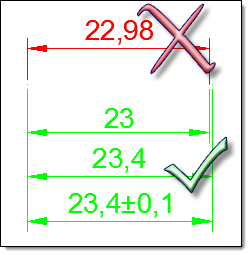 With that said, let's repeat a very important thing one more time - random or uneven dimensions such as 23,456 doesn't do any good, as it confuses more rather than illustrate proper measurements. With that said, let's repeat a very important thing one more time - random or uneven dimensions such as 23,456 doesn't do any good, as it confuses more rather than illustrate proper measurements.
It shows us that the one drawing hasn't made a consious decision of measure, as the dimension isn't accurate. Always use fitting Snaps/OSnaps and/or Direct Distance. |
We're not expecting you to choose the correct tolerance or decide allowed surface roughness. This is part of an engineers work practice, we are simply teaching you to recognize it and how this information is shown in technical drawings so that you can input it some day. |
Architectural Tolerances
Usual clearance is at least 20 mm on all sides of a window, which is then sealed and covered afterwards. It would be too expensive to let the builder work more accurately if the window, in our example, was a press fit; i.e. exact fit. Se this assembly to get the idea - Innsetting av Norges Vinduet |
We are deliberatly overlooking any complications regarding the window being leveled, as the window could be fitted into the opening regards of weather, or if the builder was having a bad day - which happens. |
| The actual window tolerances are more strict; with a usual deviation of +/- 1 mm, so finished windows are usually delivered between 589 mm and 591 mm for a standard 590 mm window, which is fitted into a 600 mm opening. |
The dimension of the door opening in the image should then read between 10-20 mm larger than the actual door width.
|
When the deviations being built (As Built) isn't being upholded the builder must use some extra time, and your money, press fit the window, or other. This is usually a simple operation when dealing with wood materials, but it might not be as simple when the object is made out of aluminum and is to be fitted in a concrete wall opening. A large part of added construction costs (may be 15% or even more) is due to corrections from incorrect tolerances, or deviations not being held. |
Mechanical Tolerances
Temperature and surface roughness will also have impact for mechanical parts. |
For mechanical parts is it important to consider the effect of one tolerance to another tolerance.
This can be done by referring all dimension to a single datum surface. The selection of the datum surface or baseline should be based on the functionality of the object. When dimensions are specified as a chain, the tolerances for the part may add up. A chained dimension uses the end of one dimension as the beginning of the next. Tolerance stacking refers to the way the tolerance for one dimension of a feature is added to the next dimension of the next feature in the chain, resulting in a large variation in the location of the last feature in the chain. Reference; Technical Drawing with engineering Graphics, Giesecke et al., 2016, s 559. |
Tolerance for holes are indicated by a capital letter (e.g. H7) and axle tolerances are indicated by a smal letter (e.g. h7). There are different passing tolerance classes for different use as loose fit, light interference fit and interference fit (press fit). |
|
|
Tolerance of Position and Form
Tolerances of form and positon control straightness, flatness, parallelism, perpendicularity, concentricity, roundness and so on.
Symbols are used to specify the tolerance. The tolerance is framed with a leader line with an arrow pointing at the specific geometry.
Datum surfaces are often used in a combination with a tolerance of position and form.
Look at Maskintegning, section 28 Form og beliggenhetstolernaser for more Information. |
Welding Symbols
Drawings with welded connections include welding symbols who specifies the detail of the weld. There are different types of welded connections and standard symbols are documented in NS and ISO standards.
Welded connections are specified by a “bent” arrow with basic symbols in combination with numeric information and supplementary symbols.
Maskintegning, section 39 Sveising, shows tables with basic and supplementary welding symbols in addition to an example of a complete welding symbol with reference information, Figur 39.1.
Arrow side
- Arrow with weld symbol above the arrow line points at the joint where the weld is to be made.
- Arrow with weld symbol below the arrow line points at the other side of the joint where the weld is to be made.
- Arrow with weld symbols on both side of the arrow line specifies welds on both sides of the joint.
Maskintegning, section 39.3 Sveisens pilside – sveisens motsatte side.
Technical Drawing with Engineering Graphics, Kapittel 21: Representation (p. 846 – 864)
We are not expecting you to have the knowledge to select type of welding method and set up welding symbols.
But you should recognize them!
Dagens Aktiviteter
Oppgave 2301
|
© Noroff Education 2019
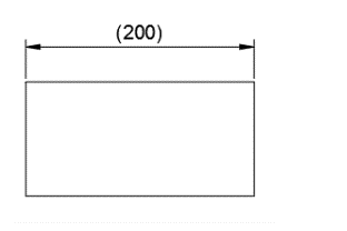 Information dimensions, also called reference dimensions may in some occasions be necessary and useful to include in the drawing, but will not affect the function of the part or relate to the tolerance table (see section on tolerances below for more information)
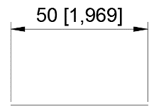 Dimensions are usually shown in millimeters when drawing according to the NS/ISO standard.
 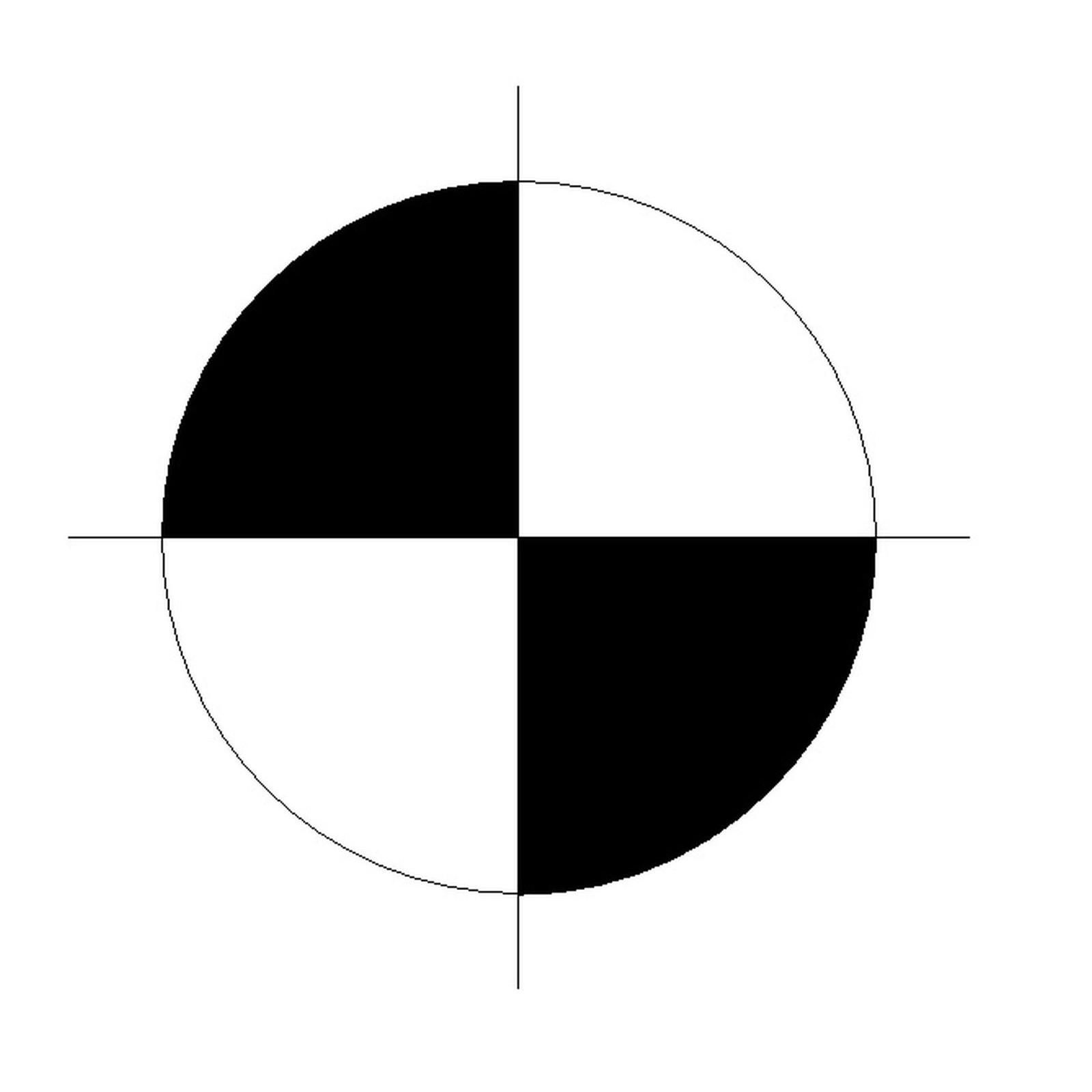 Some drawings have a datum point, a reference point where dimensions and coordinates are measured from (e.g. Foundation drawings).
 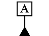 Datum Surfaces, are reference planes who that are used in conjunction with geometric tolerancing, to ensure greater accuracy on critical feature of a part. Critical features are elements that are vital for the functionality of the part. Datum surfaces are also important when inspecting the part after production.
 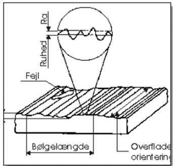 Even though the surface look smooth and shiny will a closer inspection identify rough structure and filets.
 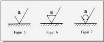 More information regarding surface roughness can be found in:
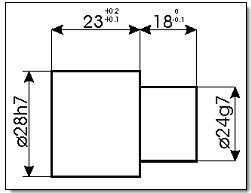 The image shows dimensions with limited tolerances and standard tolerances.
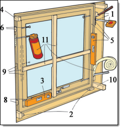 When a window is slotted into a wall the builder uses a
 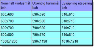 Standard dimensions on windows and doors is therefore 10 mm less than the actual measure, while the opening for placement is 10 mm wider.
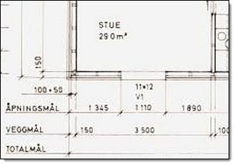 On buildings you should always take into account deviations of approximately 10 mm on each side in openings.
 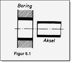 The principals for use of tolerances between architectural features and mechanical features are the same, but mechanical tolerances have usually stricter requirements for accuracy. It is therefore common to state general tolerances in mechanical drawing through a tolerance table. The most common table to be used within mechanical drawings is ISO 2768. Information regarding the table is therefore often included on the drawing, where it also specifies which tolerance class it follows (fine, medium, coarse, very coarse).
 Passing tolerances are used for parts who shall fit together as a window in a wall, or an axel in a hole. Passing tolerances indicates the clearance between the objects.
 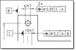 Maskintegning, section 28 Form og beliggenhetstoleranser, shows tables with