Technical Drawing 2D T2D |
|
Academic Week: AW: 04 - CAD |
Technical Drawing 2D T2D |
|
Academic Week: AW: 04 - CAD |
We will continue with dimensions and annotation of technical drawings and today we look at tolerances, which is the allowable deviations that is acceptable between the technical drawings and the manufactured product. The theory of today’s lesson is only applicable to mechanical drawings, but it is very useful and important knowledge for all drafters.
We have been looking at how to dimension drawings. What is important to remember is that there will always be deviations between the physical shape of an object and the theoretical shape specified in the technical drawings. In other words, a part is never manufactured perfectly accurate. How a manufactured part deviates from its technical drawing depend greatly on the method of production. If the part is handmade, the deviations will be larger than if it is made through an automated process. Even though automated machines such a CNC milling machines are very accurate, they are never perfect.
If a part or product cannot be manufactured with the exact dimensions specified in the drawing, how do we then ensure that the part will function as intended? The answer to this question is to define tolerances. By doing so, you are communicating the range of accuracy that is acceptable. It is then the workshops responsibility to manufacture the part within the defined tolerance range. If they fail to do this, the workshop will be the one carrying the expense of manufacturing a new part.
If you on the other hand deliver a technical drawing for manufacturing without any tolerances, you might end up having to carry the cost of replacing the part.
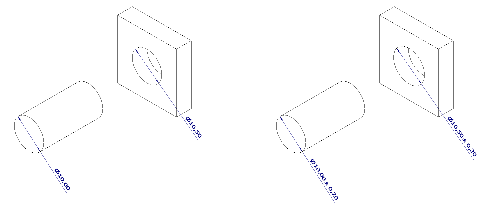
Let us take a look at a practical example. The example illustrates a shaft and a hole, where the shaft should be able to pass through the hole.

Left side
As the drawing contains no tolerances, you could argue that any measurement that is 10mm is correct for the shaft. The diameter on the produced shaft could then be anything from 10.00-10.99mm. Even if the hole is exactly 10.50mm, the shaft will not fit the hole. As a result, the workshop can claim to have manufactured the parts according to the technical drawings, and refuse to carry the cost of fixing the problem.
Right side
The drawing has a specified tolerance of ±0.2mm for both measurements. This means that the actual measurement can deviate 0.2mm from the 10mm dimension, in both positive and negative direction.
As the measurement of the shaft and hole never overlap, the shaft will always fit inside the hole as intended. If it does not fit, then the workshop did not manufacture the part according to specifications and they will have to carry the cost of fixing the problem.
As you might expect, it is costly to produce products with a high degree of accuracy. To keep the costs down, it is therefore important to specify a tolerance as large as possible that still permits satisfactory function of the part.
Before we go any further, you need to become familiar with some the size designation terms that apply in tolerancing.
If we take a new look at the shaft to the right in the example above, the different terms represents:
So far, we have covered tolerances in their most basic form, by explaining the purpose of them. Tolerancing is however, a complicated topic that takes time and practice to master. As this is your first lesson to tolerancing, we will keep it simple and focus on three ways of applying tolerances when drafting.
Before you continue. Download and open a new drawing file based on the following template, which includes the applicable tolerance table:
The Noroff template includes a tolerance table, ISO 2768-1 medium. This table includes information regarding general tolerances, and are applicable to all dimensions in the drawing unless otherwise stated. It is important to become familiar with the table, as it is widely used in the industry. All tolerances are displayed using ±, indicating that the tolerance range is even in both positive and negative direction from the nominal value.
| General Tolerances for Linear and Angular Dimensions | ISO 2768-1 | |||||||
|---|---|---|---|---|---|---|---|---|
| Tolerance Class | Linear Dimensions | |||||||
| Limit deviations in mm for nominal dimension ranges | ||||||||
| 0.5 to 3 | Over 3 to 6 | Over 6 to 30 | Over 30 to 120 | Over 12 to 400 | Over 400 to 1000 | Over 1000 to 2000 | Over 2000 to 4000 | |
| f (fine) | ±0.05 | ±0.05 | ±0.1 | ±0.15 | ±0.2 | ±0.3 | ±0.5 | - |
| m (medium) | ±0.1 | ±0.1 | ±0.2 | ±0.3 | ±0.5 | ±0.8 | ±1.2 | ±2 |
| c (coarse) | ±0.2 | ±0.3 | ±0.5 | ±0.8 | ±1.2 | ±2 | ±3 | ±4 |
| v (very coarse) | - | ±0.5 | ±1 | ±1.5 | ±2.5 | ±4 | ±6 | ±8 |
| Tolerance Class | Chamfered Edges (radii & chamfers) | Angular Dimensions | ||||||
| Limit deviations in mm for nominal dimensions ranges | Limit deviations in degrees and minutes for nominal dimension ranges (shorter angle leg) | |||||||
| 0.5 to 3 | Over 3 to 6 | 6 | To 10 | Over 10 to 50 | Over 50 to 120 | Over 120 to 400 | 400 | |
| f (fine) | ±0.2 | ±0.5 | ±1 | ±1° | ±0°30' | ±0°20' | ±0°10' | ±0°5' |
| m (medium) | ||||||||
| c (coarse) | ±0.4 | ±1 | ±2 | ±1°30' | ±1° | ±0°30' | ±0°15' | ±0°10' |
| v (very coarse) | ±3° | ±2° | ±1° | ±0°30' | ±0°20' | |||
Tolerance class: ISO 2768-1 has four different tolerance classes, depending on how precise manufacturing is required. The table used in the Noroff template uses the tolerance class m (medium).
Linear dimensions: Tolerances that apply to all linear dimensions on the drawing, unless otherwise specified. From the list, you can find tolerances for length up to 4000mm (4m). As you can read from the list, the tolerance range increases as the length of the dimension increases.
Chamfered edges (radii & chamfers): Tolerances that apply to all fillet and chamfer dimensions on the drawing, unless otherwise specified. As with linear dimensions, the tolerance range increases as the dimension of the fillet or radius increases.
Angular dimensions: Tolerances that apply to all angular dimensions on the drawing, unless otherwise specified. The tolerance range is determines by the length of the shorter angle leg. The longer the shorter angle leg, the smaller the tolerance range. Angle deviation is measured in angles (°) and minutes ('), with one minute being 1/60 of a degree.
Measurements that deviates from the general table can be specified separately. This is commonly used on important dimensions that are essential for the function of the part, and might require more precise tolerances than provided in the general tolerances.

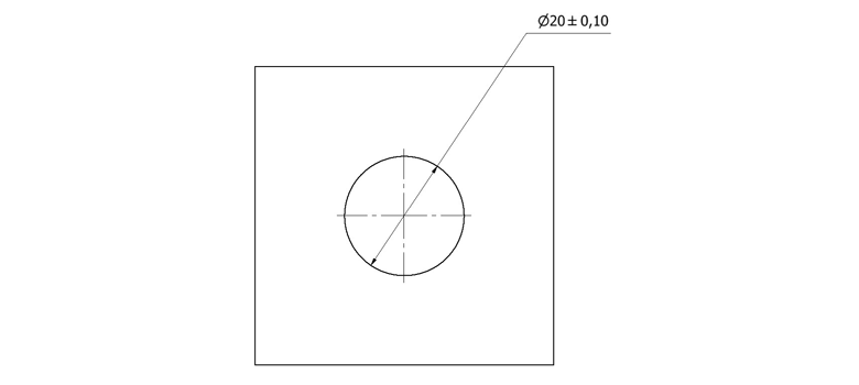
The tolerance range of the hole in the illustration above is 0.2mm, with a lower limit of 19.9mm and a upper limit of 20.1mm.
Video Demonstration: Tolerances for Specific Areas
So far, we have looked at how to add tolerances to dimensions, but we can also add tolerances to the shape of an object. This is done by the using geometrical tolerances, which are a bit more complicated than what we have covered so far. The reason they are complicated is mainly due to two reasons:
Before continuing this lesson, you must open your textbook on page 108-110 (Mechanical and Metal Trades Handbook) and browse the full list of the various geometrical characteristic’s symbols available.
You should now have an basic understanding of the various symbols and their purpose and we can move on to how they work in conjunction with datum indications.
Take a look at the example below. The geometric tolerance symbol states that we are using a perpendicular tolerance. The following number (0,1) tells the maximum deviation allowed. To explain this further, you need to imagine two parallel planes on either side of the line we are tolerancing. The distance between the two lines are 0.1mm and they are perpendicular to the line marked with the letter A. The line that has been given a geometrical tolerance must be within the area of the two parallel lines in order to be in accordance with the drawing. The datum indication (A) indicates the line we want our line to be perpendicular in relation to.
Positional geometric tolerance (or True Postion) is one of the most common geometric tolerances, and is often used to position holes with accuracy. In addition to datum indications, positional tolerances also require the input of theoretical precise dimensions. Theoretical precise dimensions are recognised by being positioned inside a frame. They display the theoretical (ideal) dimension and does not include any form of tolerance, as the tolerance is defined by the positional tolerance.
To get an understanding of how this is used, have a look at the following practical example.
Click the image to enlarge.
The dimensions 10 and 30 are put inside a frame, we are now able to identify them as theoretical precise dimensions. They tell us the theoretical (ideal) position of the holes, measured from the top and left. The frame also tells us that the general tolerance table do not apply to them. If we have a look at the diameter dimension of the hole (Ø4mm), we see that it has a box with information attached to it.

Video Demonstration: True Position
Geometrical tolerances can be confusing and challenging, and takes time to master. They are essential to learn if you want to work within the mechanical industry.
For a full list of the different annotation symbols used on technical drawings, we refer to Maskinegning on chapter 46, page 343-345. This list is very useful, and can be used whenever you discover an annotation symbol that you do not recognise.
© Noroff Education 2021